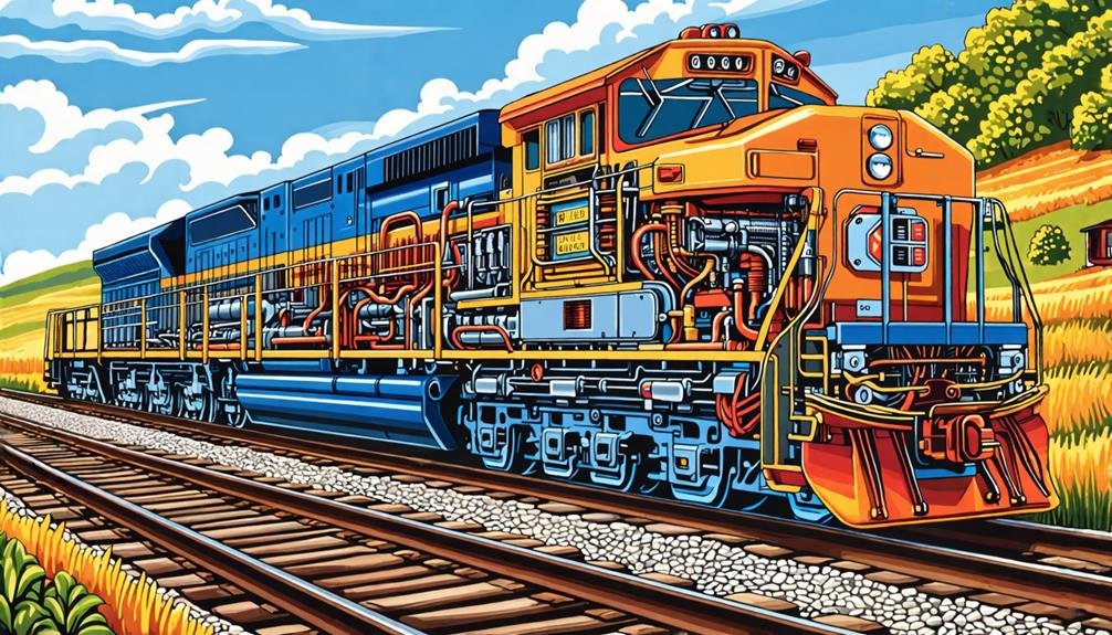
What Drives Electric Power
01.
Key Takeaways
The diesel engine acts as the prime mover, generating mechanical energy to power the main alternator. The main alternator converts mechanical energy into electrical energy, producing AC power for the locomotive. Rectifiers transform AC to DC, while inverters convert DC back to AC for efficient power distribution. Traction motors receive electrical power and convert it into mechanical force, driving the locomotive’s wheels. Advanced electronic control systems regulate power flow, optimizing efficiency and performance across varying operational demands.
02.
The Main Alternator’s Role
At the heart of a diesel-electric locomotive’s power system, you’ll find the main alternator. This essential component serves as the primary interface between the diesel engine’s mechanical energy and the electrical power required to drive the locomotive’s traction motors. As the diesel engine operates, it spins the main alternator at high speeds, typically up to 1,000 RPM, to generate alternating current (AC) electricity efficiently. The main alternator’s role extends beyond mere energy conversion. It’s a key element in the locomotive’s power transmission system, greatly enhancing mechanical efficiency compared to traditional direct-drive systems. By converting mechanical energy to electrical energy, you’re able to achieve greater flexibility and control over power distribution throughout the locomotive. You’ll notice that the main alternator’s output isn’t static. In modern systems, it can be dynamically adjusted to meet varying load demands. This adaptability allows for optimized performance across different operational conditions, ensuring that you’re always getting the most efficient power output for your current needs. The AC electricity produced by the main alternator doesn’t directly power the traction motors. Instead, it’s first rectified to direct current (DC) by a rectifier. This conversion process is essential for supplying the appropriate type of electrical energy to the traction motors, which are responsible for propelling the locomotive forward. By understanding the main alternator’s central role, you’ll gain insight into the sophisticated power flow that drives modern diesel-electric locomotives.
03.
Traction Motorsand Propulsion
Invariably, traction motors serve as the locomotive’s primary means of propulsion, converting electrical energy into mechanical force. In diesel-electric locomotives, these motors are directly connected to the axles, guaranteeing efficient power distribution and enhanced traction. You’ll find that modern designs often utilize AC traction motors due to their superior efficiency and power output compared to their DC counterparts.
04.
Load Regulation Mechanisms
Load regulation mechanisms form the backbone of efficient power distribution in diesel-electric locomotives. These systems continuously monitor and adjust the generator’s output based on engine load demands, guaranteeing peak performance across various operating conditions. You’ll find controllers that modulate the generator’s field strength, responding to real-time data from speed sensors and torque measurements.
05.
Power Distribution System
The power distribution system in diesel-electric locomotives forms the essential link between the main alternator and the traction motors. It’s responsible for efficiently channeling electrical energy from the alternator to the various components that require power, primarily the traction motors that drive the wheels. In this system, the alternator generates AC electricity, which is then rectified to DC for more effective distribution. You’ll find that this conversion process allows for better control and management of the electrical power flow throughout the locomotive. The DC power is then directed to the traction motors, typically mounted on each axle, where it’s converted back into mechanical energy to propel the locomotive forward. Advanced electronic control systems play a significant role in the power distribution process. They constantly monitor and adjust the flow of electricity to enhance performance and respond to changing operational demands. These systems guarantee that each component receives the appropriate amount of power at the right time, maximizing efficiency and reducing waste. You’ll also encounter various safety components within the power distribution system, such as circuit breakers and protective devices. These elements safeguard the electrical network from overloads and short circuits, maintaining the integrity of the system during operation. The power distribution system’s design allows for flexibility in meeting diverse operational requirements. It can adapt to varying loads, speeds, and track conditions, guaranteeing that your locomotive maintains peak performance across a range of scenarios. This adaptability is key to the overall efficiency and reliability of diesel-electric locomotives in modern rail operations.
06.
Engine-Generator Synchronization
At the heart of a diesel-electric locomotive’s power generation system lies the vital process of engine-generator synchronization. This intricate dance between the diesel engine and the generator guarantees peak power production for the locomotive’s traction motors.You’ll find that the diesel engine operates at a constant speed, acting as the prime mover in this system. It’s directly coupled to the generator, which must match the engine’s speed and torque to produce electricity efficiently. The control system plays a significant role in managing this synchronization, continuously monitoring and adjusting the generator’s output based on real-time operational conditions. As you explore deeper into the system, you’ll notice that the generator converts mechanical energy from the diesel engine into AC electricity. This power is then rectified to DC before being supplied to the traction motors. The control system’s ability to adjust the load on the generator is key to meeting the varying demands of these motors during operation. To visualize this process, imagine: A massive diesel engine roaring at a steady rhythm A generator spinning in perfect harmony with the engine Traction motors pulsing with electricity, propelling the locomotive forward The synchronization between engine and generator is not just about matching speeds; it’s about enhancing power generation efficiency. You’ll find that electronic control systems manage this process with precision, making sure that the generator’s output aligns perfectly with the engine’s capabilities and the locomotive’s power needs. This intricate balance is what drives the electric power flow in diesel-electric locomotives, enabling them to operate with remarkable efficiency and power.
07.
Efficiency in Electrical Conversion
Maximizing efficiency in electrical conversion stands as a cornerstone of diesel-electric locomotive design. You’ll find that these locomotives convert mechanical energy from the diesel engine into electrical energy through a generator or alternator. This process achieves highly efficient power generation, setting the stage for ideal performance. The rotary motion produced by the diesel engine drives the alternator, typically generating alternating current (AC) electricity. This AC is then rectified to direct current (DC) for use in traction motors. These motors, connected to the locomotive’s wheels, convert electrical energy back into mechanical energy, providing efficient power transmission with minimal energy loss.
08.
Essential EMD Power Assembly Components
Mastery of EMD locomotive rebuilds begins with understanding its power assembly components. The cylinder head forms the foundation with its valves, springs, and combustion chambers, featuring radial flow designs that enhance airflow in marine applications. The cylinder liner, available in 11-port or standard configurations, includes hardened upper bore surfaces to withstand extreme heat. Your rebuild requires high-quality pistons made from aluminum or steel, secured with snap rings for proper pin retention. Piston rings are essential for sealing combustion gases and controlling oil consumption, with low-oil variants available to reduce maintenance intervals. Regular maintenance of these components is critical as they operate under high-stress conditions that can lead to premature wear if not properly serviced. The connecting rod system consists of fork (“master”) and blade (“slave”) rods working in tandem. Fork rods contain bearing inserts for significant wear surfaces, while blade rods require precise alignment during installation. Don’t overlook grade-specific fasteners, which secure important head-to-liner joints and are typically replaced during rebuilds.
09.
Pre-Rebuild Inspection Check list
You’ll need to conduct a thorough visual assessment of all power assembly components, focusing particularly on cylinder liners for scoring and pistons for crown damage. Material testing requirements include measuring cylinder compression ratios, checking bore diameters against manufacturer specifications, and verifying rocker arm bushing hardness. Document all failure points meticulously, noting wear patterns in valve train components and any abnormal carbon deposits that could indicate combustion issues. Utilize fiber optic endoscopes for detailed internal inspection to identify potential failures before they progress to catastrophic damage.
10.
Component Visual Assessment
Before any rebuild process can begin, a thorough visual assessment of all power assembly components is critical. Using proper visual assessment techniques, you’ll need to inspect the engine block for cracks, damage, and weld integrity, particularly at the lower sump A-frame welds where structural failures commonly occur. Your inspection tools should include calibrated gauges to verify liner pilot bore alignment with manufacturer specifications. Examine all block joint seals and manifold sleeve seals for deterioration, as these are mandatory replacement items. When examining the head, look for signs of water intrusion which could indicate cracked o-rings in the head gasket. Check the top deck gasket surfaces and verify hood clamp/latch fitness. For the crankshaft assembly, confirm proper crankcase detector positioning and thoroughly inspect main bearings. Verify that all studs and bolts can achieve the required 200 ft-lbs torque specification.
11.
Material Testing Requirements
After completing the visual assessment phase, you must subject each component to rigorous material testing procedures before proceeding with the rebuild process. Begin with pressure testing to verify cooling system integrity and combustion chamber sealing using specialized pumps that identify deteriorated gaskets or cracked liners. Perform dimensional measurements with precision micrometers to validate cylinder liner tolerances and piston ring gaps according to AAR M-1003 certification standards. These testing techniques guarantee components fall within EMD specifications. Finally, conduct metallurgical analysis to evaluate material properties through hardness testing of piston crowns and fatigue crack detection on connecting rods. This testing should include the use of advanced diagnostic tools to ensure accuracy and reliability of all measurements. Apply dye penetrant or magnetic particle inspection to reveal hidden stress points. This thorough testing protocol identifies components that require replacement before assembly begins.
12.
Failure Point Documentation
Proper documentation of failure points creates the foundation for an effective locomotive power assembly rebuild. Your inspection should thoroughly identify specific failure mechanisms using multiple diagnostic approaches. Begin with boreoscopic evaluation of cylinder walls to detect scoring without full disassembly. Document dropped valves by examining bent stems and peened faces. During your failure analysis, record valve clearance issues that might have caused compression problems or knocking. When examining a cylinder, watch for signs of water intrusion which can cause catastrophic engine damage if left unaddressed. Test cooling circuits at 15-20 PSI to pinpoint hidden leaks, especially at water passage junctions where o-rings commonly fail. Use ultrasonic leak detection for micro-cracks and magnetic particle testing to identify rod cap fractures. Your documentation methods should categorize all anomalies by component type—valve, cylinder head, cooling system, or connecting rod—allowing you to establish patterns that prevent repeat failures.
13.
Disassembly Processand Best Practices
Disassembly of an EMD locomotive power assembly requires five critical stages executed in precise sequence to maintain component integrity and guarantee workplace safety. Begin by implementing lockout/tagout procedures and donning specialized PPE including heat-resistant gloves and Z87.1-rated welding helmets. You’ll need to position EMD-specific tools within reach and ascertain proper workspace organization with designated areas for components. Relieve valve train pressure by backing off injector rocker arm lock nuts before disconnecting oil supply lines Extract rocker shafts with proper support clamps while noting spring washer orientations for reassembly Position pistons at 120° after TDC for blade rod access or 22.5° for fork rod removal Secure connecting rods with dedicated clamps to prevent sleeve damage during extraction These disassembly techniques require methodical execution in a properly ventilated workspace with explosion-proof lighting. The complete power assembly weighs approximately 440 pounds with a fork rod installed, requiring adequate lifting equipment for safe handling. Remember to tag components systematically for efficient cataloging and subsequent reassembly.
14.
Critical Component Analysis and Measurement
When rebuilding an EMD locomotive power assembly, systematic inspection of all critical components is essential for ensuring operational reliability. This includes precise measurement of piston rings, cylinder liners, and valve seats to verify they meet manufacturer specifications. Regular inspection of electrical components such as alternators, traction motors, and circuit breakers should be performed as part of the rebuilding process to maintain system integrity and prevent potential failures.
15.
Cleaning and Reconditioning Procedures
Once the critical component measurements have been documented, you’ll need to thoroughly clean and recondition all power assembly elements before rebuilding. Implement a systematic cleaning approach, starting with high-pressure washing of external surfaces to remove accumulated grime. For precision parts requiring deeper cleaning, utilize ultrasonic methods to eliminate contaminants without causing surface damage. Proper cleaning is essential to prevent water in cylinder issues that could lead to catastrophic engine damage if overlooked. Apply chemical stripping with AAR/EMD-approved solvents to remove protective coatings and old lubricants from critical surfaces Utilize wire brushing techniques on cylinder liners to address corrosion while maintaining surface integrity Implement thermal cleaning in controlled environments for complex components requiring complete contamination removal Perform post-cleaning inspection to verify all oil passages and cooling channels are completely debris-free Your reconditioning techniques should match manufacturer specifications, ensuring each component meets dimensional tolerances before proceeding to reassembly. Remember to maintain vertical workspace organization throughout the cleaning process to prevent cross-contamination between cleaned and uncleaned parts.
16.
Component Replacement Guidelines
Proper component replacement represents the cornerstone of successful EMD locomotive power assembly rebuilding. When selecting replacement parts, you must adhere strictly to engine model-specific requirements. If you’re working with 567C engines, you can incorporate 645 power assemblies, but only after completing necessary upgrades to camshafts, injectors, and blower ratios. Never mix 567 and 645 assemblies within the same engine, as this compromises component compatibility and engine performance. Pay particular attention to blade and fork rod pairings. These components share a common connecting-rod journal in V-type engines, with blade rods fitting inside fork rods in a “basket” arrangement that retains both components. This precise fit is critical for proper operation. Thorough inspection for internal failures using fiber optic endoscopes provides better evaluation of components before replacement. For aftermarket considerations, select only parts meeting OEM specifications. Manufacturers like NRE offer both new and remanufactured power assemblies specifically designed for your engine model, ensuring reliability and compliance with industry standards.
17.
Testing and Quality Verification Methods
You’ll need to verify tolerances through precise clearance measurements to guarantee proper piston-to-liner fit and bearing surface integrity. For effective load testing, you must operate the power assembly under controlled conditions, monitoring oil pressure, temperature, and vibration according to ETS specifications. Verify performance by checking compression ratios and conducting blow-by tests, comparing results against the 95-second benchmark for acceptable sealing integrity.
18.
Clearance Measurement Protocols
When establishing proper tolerances between critical components in EMD locomotive power assemblies, meticulous clearance measurement becomes the foundation of reliable engine performance. You must understand the distinction between radial and diametric clearances, with radial being half the diametric measurement. Always select the appropriate measurement tools based on clearance types—feeler gauges for diametric measurements, dial indicators for longitudinal clearances, and micrometers for precise component sizing. Calculate bearing clearances by subtracting shaft OD from bearing ID Verify crankshaft alignment using dial indicators Use lead ribbon between components to measure precise contact clearances Apply proper torque sequences (500-800 ft-lb) to guarantee accurate measurements For main bearing bores, maintain specifications between 8.249″-8.252″ with out-of-round tolerances not exceeding 0.003″ when torqued to 650 ft-lb
19.
Load Testing Procedures
With proper clearances established, load testing procedures represent the definitive validation of your rebuild quality. Apply APTA PR-E-RP-003-98 standards to adjust horsepower readings for ambient conditions and evaluate true performance.Utilize resistive load boxes to simulate real-world conditions while monitoring critical parameters. You’ll need to maintain operating temperatures between 650-920°C during thermal evaluation cycles. Conduct both partial and full load tests to verify steady-state performance and transient response characteristics. This thorough load calibration guarantees your power assembly meets all performance evaluation criteria.
20.
How Often Should EMD Power Assemblies Be Rebuilt?
You should rebuild EMD power assemblies every 1,000,000 miles for 710-series engines or approximately every 7 years for locomotives operating under 100,000 miles annually. The 645E3 engine requires replacements every 20 years. Your maintenance schedule should account for operating conditions, with high-speed services needing more frequent rebuilds. Monitor rebuild frequency through regular inspections and adjust based on wear metrics like cylinder ring degradation.
21.
Can Damaged Liners Be Reused if Properly Honed?
You can reuse damaged liners after proper honing, but only if they meet specific criteria. During liner inspection, verify that damage is limited to minor surface scoring without cracks or structural compromise. Honing techniques can address light wear by restoring crosshatch patterns and surface finish, but can’t repair deep scoring, cracks, or compromised gasket interfaces. Always verify post-honing dimensions remain within OEM specifications (±0.0005″ concentricity) and perform pressure testing afterward.
22.
What Causes Premature Piston Ring Wear?
You’ll find premature piston ring wear stems primarily from inadequate lubrication quality. When oil levels drop or become contaminated with abrasives, the protective film between ring and cylinder wall breaks down. Thermal stress accelerates deterioration through expansion/contraction cycles that weaken piston ring materials. Poor combustion creates carbon deposits that interfere with ring movement, while improper break-in procedures can prevent rings from properly seating against cylinder walls.
23.
Are After market Components Reliable for EMD Rebuilds?
You’re rolling the dice with aftermarket components for EMD rebuilds. While cost-attractive, aftermarket quality varies considerably between manufacturers. Component compatibility remains a critical concern—material properties and dimensional tolerances must precisely match OEM specifications. You’ll face increased reliability risks, potential certification complications, and compatibility challenges. For mission-critical applications, OEM parts provide superior reliability. If using aftermarket components, source from reputable suppliers with proven testing protocols and documented quality systems.
24.
How Do Environmental Conditions Affect Rebuild Intervals?
Environmental conditions considerably impact your rebuild intervals. Extreme temperature fluctuations create thermal stress that accelerates component fatigue, particularly in power assemblies and cooling systems. High humidity levels promote corrosion on cylinder liners and metal surfaces, necessitating more frequent rebuilds. Operating in coastal areas with salt air or regions with severe weather conditions further degrades components. You’ll need to adjust your maintenance schedule by 15-30% when locomotives operate in harsh environmental zones.